new
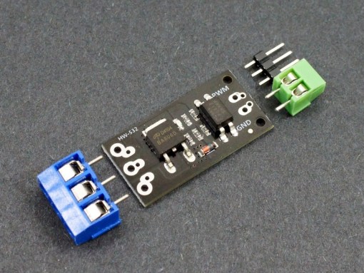
D4184 MOSFET Control Module
The module includes a PC817 optoisolator which provides electrical isolation between the high powered MOSFET side and the logic signals used to control the module. If something goes wrong and you burn up the MOSFET, it should not damage the MCU being used to control it.
The MCU PWM input to the module drives the internal LED side of the optoisolator. This input includes a 1K ohm series current limiting resistor to keep the current through the LED at safe levels which allows the input to be driven by up to a 20V input or even higher if you are not using an MCU.
When the PWM input signal is low or disconnected, the internal LED in the optoisolator is off which in turn keeps the phototransistor output turned off. With the phototransistor off, the gate of the MOSFET is pulled to ground by a 4.7K resistor. This keeps the MOSFET turned off and the load is disconnected from ground and disbled.
A logic high on the PWM input turns on the internal optoisolator LED which turns on the phototransistor. This creates a voltage divider composed primarily of two 4.7K resistors. This biases the gate at 50% of the power supply voltage which turns on the MOSFET. If a 12V power supply is used, the gate will be at 6V.
Since the maximum gate voltage available to turn on the MOSFET is 50% of the power supply voltage, that limits the power supply to a minimum of about 6V. Power dissipation in the MOSFET will be higher with lower power supply voltages and a minimum power supply of 9V is recommended if trying to draw more than a few amps through the module.
When the MOSFET conducts, the load is connected to ground to complete the circuit and the load is powered up. This also provides a ground for the on-board LED which lights to indicate that the MOSFET is turned on. A 4.7K resistor limits current through the on-board LED to safe levels over the 6-36V operating range.
Module Connections
The module requires 3 connections. A logic signal to turn the MOSFET on/off; a DC power supply to power the device (load) being controlled and finally the load itself. Connectors are provided that can be soldered to be the board, but these connections can also be made by direct wiring if desired.
